Inverse kinematics solves for the joint angles given the desired position and orientation in Cartesian space. This is a more difficult problem than forward kinematics. The complexity of inverse kinematics can be described as follows, Given a 4x4 homogeneous transformation which gives the required position and orientation
The homogeneous transformation matrix results in 12 nonlinear equations in 16-unknown
variables ( ![]() ).
).
where i=1,2,3 , j=1,2,3,4.
For example, to find the corresponding joint variables
( ![]() ) for RRP:RRR
manipulator shown in Figure 2 where
) for RRP:RRR
manipulator shown in Figure 2 where
we must solve 12 simultaneous set of nonlinear equations. See (Appendix A). The first glance at a simple homogeneous transformation matrix eliminates the possibility of finding the solution by solving those 12 simultaneous set of nonlinear trigonometric equations. These equations are much too difficult to solve directly in closed form and therefore we need to develop efficient techniques that solves for the particular kinematics structure of the manipulator. To solve the inverse kinematics problem, closed form solution of the equations or a numerical solution could be used. Closed form solution is preferable because in many applications where the manipulator supports or is to be supported by a sensory system, the results need to be supplied rapidly (in real-time) [1]. Since inverse kinematics can result in a range of solutions rather than a unique one, finding a closed form solution will make it easy to implement the fastest possible sensory tracking algorithm.
One aim of this work is to try to find closed solutions for a prototype robot which is a general 3 - DOF robot having an arbitrary kinematic configuration connected to a spherical wrist. These closed form solutions could be attained by different approaches [3, 6, 7]. One possible approach is to decouple the inverse kinematics problem into two simpler problems, known respectively, as inverse position kinematics, and inverse orientation kinematics [1, 3]. To put it in another way, for a six-DOF manipulator with a spherical wrist, the inverse kinematics problem may be separated into two simpler problems, by first finding the position of the intersection of the wrist axes,the center,and then finding the orientation of the wrist. Lets suppose that there are exactly six degrees of freedom and the last three joints axes intersect at a point O. We express the rotational and positional equations as
where d and R are the given position and orientation of the tool frame.
The assumption of a spherical wrist means that the axes ![]() and
and ![]() intersects
at O and hence the origins
intersects
at O and hence the origins ![]() and
and ![]() assigned by the D-H convention will
always be at the wrist center O.
The importance of this assumption for inverse kinematics is that the motion of the final
three links about these axes will not change the position of O. The position of the wrist
center is thus a function only of the first three joint variables. Since the origin of the tool
frame
assigned by the D-H convention will
always be at the wrist center O.
The importance of this assumption for inverse kinematics is that the motion of the final
three links about these axes will not change the position of O. The position of the wrist
center is thus a function only of the first three joint variables. Since the origin of the tool
frame ![]() is simply a translation by a distance
is simply a translation by a distance ![]() along the
along the ![]() axes from
O, the vector
axes from
O, the vector ![]() in the frame
in the frame ![]() is
is
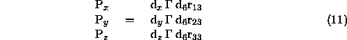
Note that R is multiplied by k because it is a translation along z axes.
Suppose ![]() denotes the vector from the origin of the base frame to the wrist center.
Thus, in order to have the end-effector of the robot at the point d with the orientation of
the wrist center O located at the point
denotes the vector from the origin of the base frame to the wrist center.
Thus, in order to have the end-effector of the robot at the point d with the orientation of
the wrist center O located at the point
the orientation of the frame ![]() with respect to the base is given
by R. If the components of the end-effector position d are denoted by
with respect to the base is given
by R. If the components of the end-effector position d are denoted by
![]() and the components of the wrist center
and the components of the wrist center ![]() are denoted by
are denoted by
![]() then this equation results in the relationship
then this equation results in the relationship
Using equation 10 we may find the values of the first three joint variable. Thus for this class of manipulators, the determination of the inverse kinematics can be summarized in 3 steps [1]: