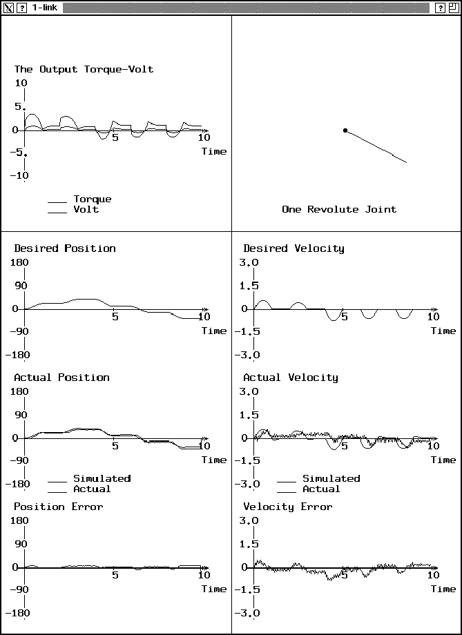
Figure 44: The behavior of the one-link robot for the first input sequence.
Building the three-link robot has passed through several stages until the final version was reached. As mentioned before, The first phase was controlling a one-link robot.
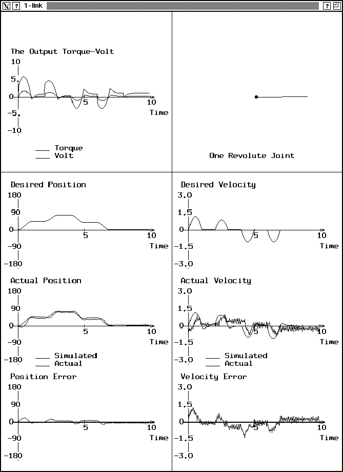
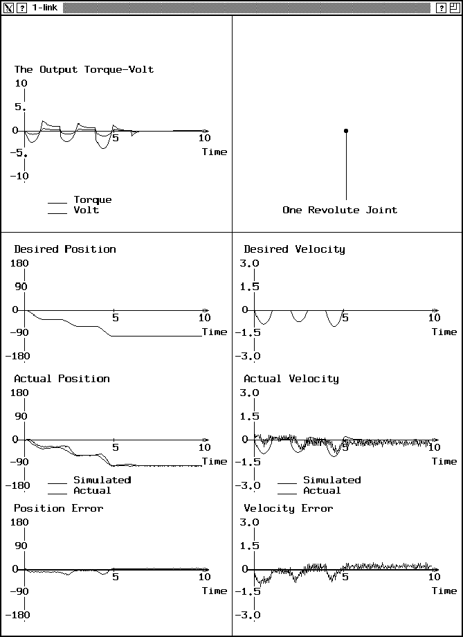
Three input sequences have been used for the desired positions, and after applying the voltage files to the motor using the I/O card, the actual positions and velocities are measured using a potentiometer for the position, and a tachometer for the angular velocity. These measured values are saved in other files, then a graphical simulation program was used to display the movement of the link, the desired and actual positions, the desired and actual velocity, and the error in position and velocity. Figures 44, 45, and 46 show the output windows displaying the link and graphs for the position and the velocity.

Figure 44: The behavior of the one-link robot for the first input sequence.

Figure 45: The behavior of the one-link robot for the second input sequence.

Figure 46: The behavior of the one-link robot for the third input sequence.