This simulator was used to give some rough estimates about the required design parameters such as link lengths, link masses, update rate, feedback gains, etc. It is also used in the benchmarking described earlier. Figure 47 shows the simulated behavior of a three-link robot. It shows the desired and actual position and velocity for each link and the error for each of them. It also shows a line drawing for the robot from two different view points.
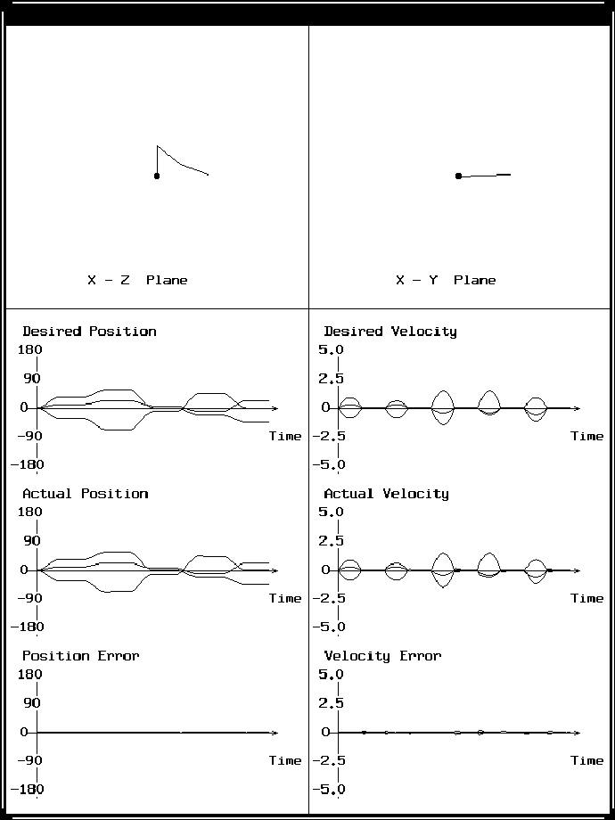
Figure 47: The output window of the simulator for the three-link robot.
This simulator uses an approximate dynamic model for the robot, and it allows any of the design parameters to be changed. For example, the effect of changing the update rate on the position error is shown in Figure 48. From this figure, it is clear that increasing the update rate decreases the position error.
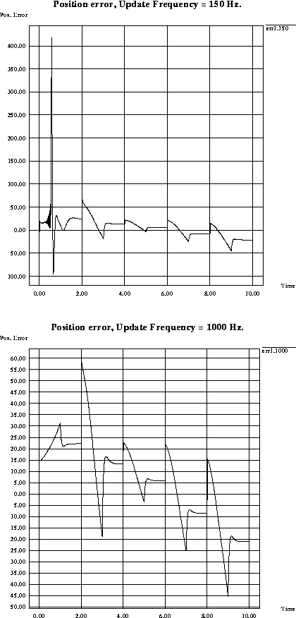
Figure 48: The effect of changing the update rate on the position error.