![]()
![]() Index:
Index:
![]()
The main objective of this project is to determine the Singularity Configuration of desired manipulator and to avoide the manipulator to pass through that Singularity Configuration so as to obtain maximum efficiency from the Robot.
![]()
The Jacobian, in robotics, is a matrix-valued function which can be thought of as the vector version of the ordinary derivatives of a scalar function. The forward kinematic equations of the robot define a function between the space of cartesian positions and orientations and the space of joint positions mathematically. From this, the velocity relationships are then calculated / determined by the Jacobian of the function.
When the value of the determinent of the Jacobian function is zero then this configuration of the manipulator is refered to as Singularity Configuration. The identification and avoidance of singularities or singualrity configurations is very important in Robotics. Some of the main reasons are:
1) Singularities represent configurations from which certain directions of motion may be unattainable.
2) At singularities, bounded gripper velocities may correspont to unbounded joint velocities.
3) At singularities, bounded gripper forces and torques may correspond to unbounded joint torques.
4) Singularities usually (but not always) correspond to points on the boundary of themanipulator workspace, that is, to points of maximum reach of the manipulator.
5) Singularities correspond to points in the manipulator workspace that may be unreachable under small perturbations of the link parameters, such as length, offset, etc.
6) Near singularities there will not exist a unique solution to the inverse kinematics problem. In such cases there may be no solution or there may be infinitely many solutions.
"Craig, John J., ``Introduction to Robotics Mechanics and Control"
![]()
The word robot originated from the Czech word robota, meaning work. Webster's dictionary defines robot as "an automatic device that performs functions ordinarily ascribed to human beings." A definition used by the Robot Institute of America gives a more precise description of industrial robots: "A robot is a reprogrammable multi-functional manipulator designed to move materials, parts, tools, or special-variety of tasks." In short, a robot is a programmable general-purpose manipulator with external sensors that can perform various assembly tasks. With this defination, a robot must possess intelligence, which is normally due to computer algorithms associated with its control and sening systems. (Robotics: Control, Sensing, Vision, and Intelligence page1)
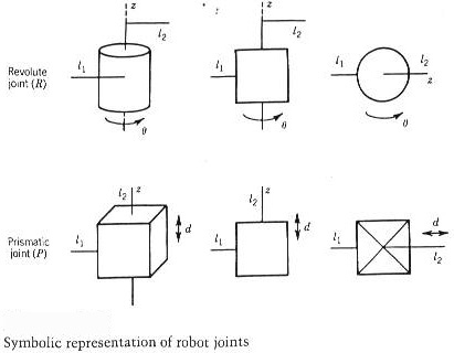
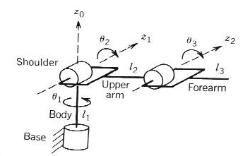
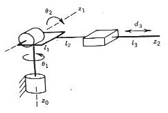
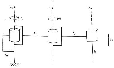
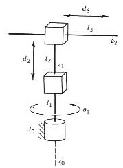
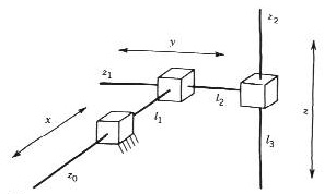
Robots are the general-purpose, computer-controlled manipulator consisting of several rigid links connected by joints into an open kinematic chain. Joints are typically rotary (revolute) or linear (prismatic). A revolute joint is like a hinge and allows relative rotation between two links. A prismatic joint allows a linear relative motion between two links. The convention (R) is used to represent revolute joint and convention (P) is used to denote prismatic joints. The joints are shown in the figure. Each joint represents the interconnection between two links, li li+1. Similarly, the axis of rotation of a revolute joint, or the axis along which a prismatic joint slides is represented by zi if the joint is the interconnection of links i and i+1. The joint variables, denoted by (theta)i for a revolute and 'd' for a prismatic joint, represent the relative displacement between adjacent links.
The number of joints of a manipulator determnes the degrees-of-freedom (DEO) of the manipulator. Typically manipulator should possess at least six DOF: three for positioning and three for orientation. A manipulator having more than six links is referred to as a kinematically redundant manipulator.
The workspace of a manipulator is the total volume swept out by the end-effector as the manipulator executes all possible. There are two types of workspace: a reachable workspace and a dextrous workspace.
![]()
Mechanically, a robot is composed of an arm (or mainframe) and a wrist subassembly plus a tool. It is designed to reach a workpiece located within its work volume. The work volume is the sphere of influence of a robot whose arm can deliver the wrist subassembly unit to any point within the sphere. The arm subassembly generally can move with three degrees of freedom. The combination of the movements positions the wrist unit at the workpiece. The wrist subassembly unit usually consists of three rotary motions. The combination of these motions orients the tool according to the configuration of the object for ease in pickup. These last three motions are often called pitch, yaw, and roll; as shown in the figure. Hence, for a six-jointed robot, the arm subassembly is the position mechanism, while the wrist subassembly is the orientation mechanism. These concepts are illustrated by the Cincinnati Milacron T robot and the Unimation PUMA robot arm as shown in the figure.
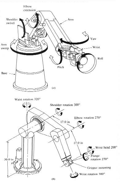
(a) Cincinnati Milacron T3 robot arm. (b) PUMA 560 series robot arm

Structure of a spherical wrist.
![]()
![]() Classification of Robot
Manipulator:
Classification of Robot
Manipulator:
Robot manipulators can be classified into various groups depending on their geometry, shape, kinematic structure and application type desired. Besed on geometry, manipulators are divided into these five types: articulated (RRR), spherical (RRP), SCARA (RRP), cylindrical (RPP), and cartesian (PPP).
I have written a program in JAVA to determine singularity of the following configurations. Please click out any of these and test yourself whether your given input results in singularity or not.
1) RRR
2) RRP
3) RPR
4) PRR
5) PPP
6) PPR
7) PRP
8) RPP
![]()
![]() Forward Kinematics
and the D-H Representation
Forward Kinematics
and the D-H Representation
Forward Kinematics is a process in which we determine the position and orientation of the end-effector, given the joint variables of the robot. The joint variables are the angles between the links in the case of revolute or rotational joints, and the link extension in the case of prismatic or sliding joints.
A commonly used convention for selecting frames of reference in robotic applications is the Denavit-Hartenberg, or D-H convention. In this convention, each homogenous transformation Ai is represented as a product of four "basic" transformation
Ai = Rotz,theta(i) Transz,d(i) Transx,a(i) Rotx,alpha(i)
where ai is called the lenght, alpha(i) is called the twist, di is called the offset, and theta(i) is called the angle.
Please see Chapter Three on Craig, John J., ``Introduction to Robotics Mechanics and Control'',
The general procedure to determine forward kinematics using D-H convention can be summarized as:
Step1: Locate and label the joint axes z0 ........... zn-1
Step2: Establish the base frame. Set the origin anywhere on the z0 - axis. The x0 and y0 axes are chosen conveniently to form a right-hand frame.
For i = 1, ........... n-1, perform Steps 3 to 5.
Step3: Locate the origin oi where the common normal to zi and zi-1 intersects zi. If zi intersects zi-1 locate oi at this intersection. If zi and zi-1 are paralled, locate oi at joint i.
Step 4: Establish x along the common normal between zi-1 and zi through oi, or in the direction normal to the zi-1-zi plane if zi-1 and zi intersect.
Step5: Establish y to complete a right-hand frame.
Step6: Establish the end-effector from oxyz. Assuming the n-th joint is revolute, set k = a along the direction z. Establish the origin o conveniently along z, prefreably at the center of the gripper or at the tip of any tool that the manipulator may be carrying, Set j = s in the direction of the gripper closure and set i = n as s*a. If the tool is not a simple gripper set x and y conveniently to form a right-hand frame.
Step7: Create a table of link parameters a, d, alpha, theta.
a = distance along x from o to the intersection of the x and z axes.
d = distance along z from o to the intersection of the x and z axes. d is variable if joint i is prismatic.
alpha = the angle between z and z measured about x (see figure).
theta = the angle between x and x measured aobut z. Theta is variable if joint i is revolute.
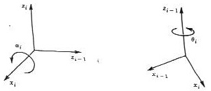
Positive sense for alpha and theta
![]()
The software used for this projects are Maple tools and JAVA Developer Kit (JDK). First, for each configuration the D-H parameters were determined and placed on Maple. After this, the Forward kinematic was calculated using Maple. Thus, jacobine matrix of the manipulator determined.
This jacobine matix was used to decouple the singularities of the manipulator. As seen earlier that singularities can be decoupled into two different types arm singularities and wrist singularities if robot has 6 or more degree of freedom. The arm singularities is the one resulting from motion of the arm, which consists of the first three or more links. The wrist singularities is the result of motion of the spherical wrist.
This project is designed to determine only the arm singularities of 6 degree freedom robot.
Lets assume that n = 6 (6 degree of freedom) with a 3-DOF arm and a 3-DOF spherical wrist. So the Jacobine is a 6 x 6 matirx and a configuration q is singular if and only if
det J (q) = 0
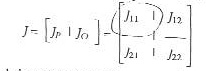
Lets now partition the Jacobine J into 3 x 3 block as
as we are using spherical wrist, so final three joints are always rebolute
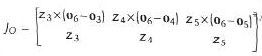
Since the wrist axes intersect at a common point o, if we choose the coordinate frames so that o3 = o4 = o5 = o6 = 0, then J0 becomes
![]()
and the i-th column Ji of Jp is :
![]()
if the joint i is revolute then

if the joint i is prismatic, then the Jacobine matrix has the block triangular form as:
![]()
with the determinent
det J = det J11 det J22
where J11 and J22 are both 3 x 3 matrix. J11 has its i-th column zi-1 x (o - oi-1) if joint i is revolute, and zi-1 if joint i is prismatic, and
J22 = [ z3 z4 z5 ]
So if we have det J11 = 0 then we will obtain arm singularities and if J22 = 0 then we will get wrist singularities.
The determinent det J11 thus obtained from Maple software gives the expression of the combination of theta, alpha, d, and a. This expression was put on Java Program. Basically 6 theta's, 6 alpha's, 6 d's, and 6 a's are the input of the program. When all the input are given, the program will evaluate the numerical value of det J11 and if the result is equvalent to zero, it will display "Alert! ............ the given condition is singualrity"; else if the result is not zero then it will display "Proceed............ the given configuration is not Singularity". Please check the Java source code for further information.
![]()
Robots are expensive insturment and complicated design. It is very important for every individual to take maximum efficiency out of each robot. Singularity is one of the major porblems in the movement of robot manipulators. Once robot reach singularity configuration, it stops its movement and the system should be started again. This will result in waste of time and energy, and expence as well. So, determination of singularity configuration in robot movement and its avoidance is of importance in robotic industry. If we encounter singularity configuration then immediately we can choose the alternative path for robot movement.
The Java program written to determine singularity configuration is accessible to every World-Wide-Web surfers. The Java Applets enable any user to check whether their own input result leads to singularity or not.
This project also gives a basis to the fact that any robot can be controlled by the users from any part of the world through the means of today's growing technology of Internet and World-Wide-Web, with the condition that both user and robot are connected with server / system.
This project also provieds basis to rapidly growing and popular distance-learning program in the field of Robotics thrgouth the Internet.
![]()
Craig, J. Introduction To Robotics. Addison-Wesley, 1989.
Everett, H. R. Sensors for Mobile Robots: Theory and Application. A K Peters, Ltd. MA 1995
Fu, S. K., R. C. Gonzalez, and C. S. G. Lee ROBOTICS: Control, Sensing, Vision, and Intelligence. McGraw-Hill Book Company, 1987
Mark W. Spong and M. Vidyasagar, ``Robot Dynamics and Control'', John Wiley & Sons.
Sobh, T. M., Dekhil, M., AND Henderson, T. C. Prototyping a robot manipulator and controller. Tech. Rep. UUCS-93-013, Univ. of Utah, June 1993.
![]()
Adobe Photoshop
Java Developer Kit
Maple V Release 4
![]()
![]() To RISC
lab of University of Bridgeport.
To RISC
lab of University of Bridgeport.