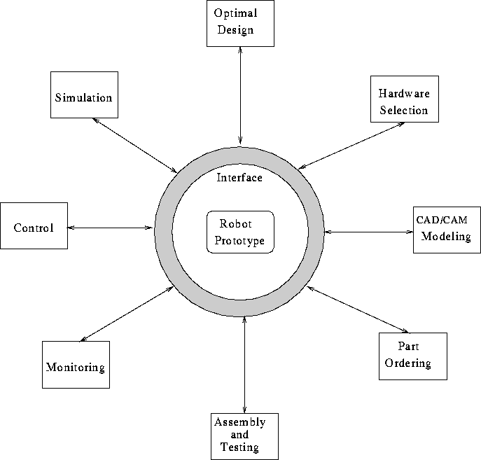
Figure 29: Schematic view for the robot prototyping environment.
The prototyping environment consists of several subsystems such as:
Figure 29 shows a schematic view of the prototyping environment with its subsystems and the interface.

Figure 29: Schematic view for the robot prototyping environment.
These subsystems share many parameters and information. To maintain the integrity and consistency of the whole system, a central interface (CI) is proposed with the required rules and protocols for passing information. This interface will be the layer between the robot prototype and the subsystems, and it will also serve as a communication channel between the different subsystems.
The tasks of this interface include:
The difficulty of building such an interface arises from the fact that it deals with different systems, each with its own architecture, knowledge base, and reasoning mechanisms. In order to make these systems cooperate to maintain the consistency of the whole system, we have to understand the nature of the reasoning strategy for each subsystem, and the best way of transforming the information to and from each of them.
In this environment the human role should be specified and a decision should be taken about which systems can be fully automated and which should be interactive with the user. The following example illustrates the mechanism of this interface and the way these systems can communicate to maintain system consistency.
Assume that the designer wants to change the length of one of the links and wants to see what the motor parameters should be that give the same performance requirements. The optimal design subsystem is used to determine the new values for the motor parameters given the new length, then it sends a request to the CI to look for the motor with the required specifications in the part-ordering system. Here we have two cases: a motor with the required specifications is found in the catalogs, or no motor is available with this specification. In the second case, this will be reported and another motor with the closest specifications will be selected. Next, the motor specifications will be updated in the database; then the CAD/CAM system is used to generate the new model and to check the feasibility of the new design. For example, the new motor might have a very high rpm, which requires gears with high reduction ratio. This might not be possible in some cases when the link length is relatively small. In this case, this will be reported and the user will be notified of this problem and will be asked to either change some of the parameters or the performance requirements and the loop will start again. Once the parameters are determined, the monitoring program is used to give a performance analysis and compare the results with the required performance. Finally, a report with the results is produced.