Theory behind the project:
Basis for the mathematical computations were obtained mostly from a single source, "Robot Dynamics and Control" by Spong, but were widely supported and/or compared with various sources on the Internet as well as several other books written on the subject of robotics. During first several weeks of the project, development of the necessary computational formulas was at a virtual stand-still. Further progress of the project was dictated by the implementation of computational formulas as Java code. A decision was made to start from scratch and question every statement, every formula related to the project no matter how insignificant it might have been. Surprisingly enough, this proved the original formulas to be wrong, therefore, it was necessary to conduct mathematical calculations all over again.
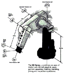
Puma 560 is a not so complex, six degree-of-freedom (DOF) elbow manipulator as it can be seen in Fig. 1.

Forward kinematics (FK) was nothing more than a trivial case of
constructing a Denavit-Hartenberg (D-H) transformation matrix
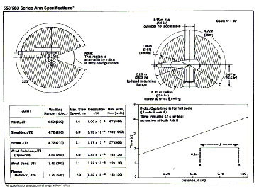
with Puma's parameters obtained from a D-H parameter table (Fig.
2).
 (deg) (deg) |  (deg) (deg) | |||
The final matrix itself can be obtained by successive multiplication
of transformation and/or rotation matrices defined by the architecture
of the manipulator (Fig.3).


When multiplied, from the form of final transformation matrix
we take elements (4,1), (4,2), and (4,3) which give us the position
of frame 6 in three-space relative to frame 0 (Fig. 3.1).


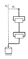
Consisting of three links and a spherical wrist, architecturally
speaking, it was obvious kinematic decoupling was the way to go
for inverse kinematics (IK) computations. The very idea of kinematic
decoupling is to separate inverse position kinematics computations
from inverse orientation kinematics computations. This can be
achieved if we consider the three links of Puma separately from
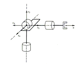
the spherical wrist. Given the architecture of Puma (Fig. 4),
it can be seen that the wrist's center of rotation, in other words,
origin of the wrist's transformation frame overlaps with the origin
of the third link's transformation frame (Fig. 5).
Considering the case of this theoretical Puma 560 model where
we have no tool mounted on the wrist, we need not include spherical
wrist position computations in final formulas for the IK position
calculation.
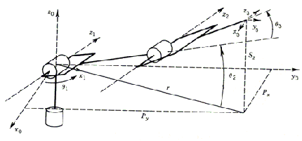
In case of Puma manipulators, where there is an offset  between links one and two (Fig. 6), a possibility of a singular
configuration does not exist. This would be a case when and only
when the wrist center intersects the
  axis.
axis.
This way, there will be only two solutions for  ,
corresponding to the so called left arm and right arm
configurations as shown in Figure 7. For the purpose of this project,
we chose a right arm configured Puma 560.
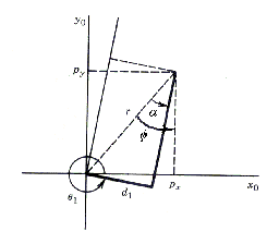
When we look at the robot from the above (Fig. 7), and pretend
that links two and three are just as one, it is easily observed
that we can obtain the magnitude of  via
simple trigonometry:


 Equation 1
Note: Please do not confuse  from
those equations and Figures 6 and 7 with
  from the D-H parameter table. The first one is actually a displacement
from links two and three combined to the
  axis of rotation of link one and can be found in D-H table as
 , further in this text denoted as
  .
.
Further, to find angles  and
and  for the elbow manipulator, given
  , we
consider the plane formed by the second and third links as shown
in Figure 8.
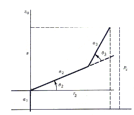
Since the motion of links two and three is planar, we can obtain
the value for  with the application of
the Law of Cosines:


and therefore  is given by:

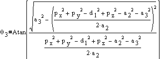 Equation 2
Similarly  is given as:


 Equation 3
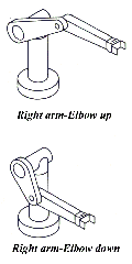
Make a note that the square roots from the equations of  and
and  have two possible solutions which
correspond to the left-arm, right-arm and elbow-up position, and
elbow-down position, respectively (Fig. 9). This gives us two
possible solutions for both
  and
and  resulting in a total of four possible solutions for
  . Therefore, we have a total of four possible combinations for
IK at a given position of the spherical wrist.
The orientation of the spherical wrist can be achieved as an
application of rotation angles (Fig. 10) from within the program.
No calculations had to be made within the FK computations. As
far as inverse orientation goes, in order to obtain the values
of wrist rotation angles we can define this as a problem of finding
a set of Euler angles corresponding to a rotation matrix from
frame three to frame six. This subject of the project is explained
in greater detail in "Robot Dynamics And Control" by
Spong in chapter 4.4, and in "Introduction To Robotics"
by Craig in chapter 4.7.
Next...Programming approach and conclusions...