Industrial Inspection and
Previous: Introduction
The vision system provides the controlling agent with specific information
about the current state of the inspection. This is done though several
layers of vision processing and through the cooperation of 2D,
2D, and 3D vision processors.
The aspects of the image that need to be given to the state machine are:
Items 1 through 4 above are accomplished using standard 2-D image processing algorithms. By assuming control of the environment, we can select the background color and texture, the lighting conditions, and some of the probe's visual characteristics to make the part distinctive in a scene. After doing so, we can use simple thresholding to locate the part and probe in an image. The part is assumed to be present in the scene, and have no intersection with the image's border. The probe is assumed to intersect the border and have a distinctly different intensity than the part.
Edge detection, via a zero-crossing algorithm, is used to detect the visual discontinuities of a part. Edge responses which are sufficiently strong and of sufficient length are considered to be contours. These contours are stored as ``chains'', derived by edge following routines.
Contours which form closed curves are considered to be portions of a mechanical feature's boundary (see assumptions below). Those which form open curves may be attributed to occlusion of one geometric feature by another (or the probe) or other factors such as lighting problems (shadows or reflections). We attempt to avoid occlusions by selecting views appropriately and lighting problems by providing a diffuse light source and a well buffed part.
2-d vision is also used to determine the relationship between these contours.
This relationship is determined in either of two ways: by region growing or
by casting two-dimensional rays. The first method should be self-explanatory.
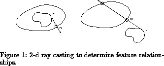
The second method works by selecting points ( and
) on two contours,
A and B (see Figure 1). To test if A is within B, a ray is
cast from
to
, counting
the number of intersections with B. If the number is odd, then A is within
B, otherwise it is not. This method works as long as the ray is not tangential
to B, a condition that can be checked and avoided.
Once the part's contours and their relationships have been determined, and the probe located in the scene, the proximity (in image coordinates) of the probe tip to a feature allows us to determine the state of the inspection. Example states include:
In order to transform our 2-d contours into three dimensions, we implemented a stereo vision algorithm by Aloimonos[2]. This algorithm can compute the depth of a planar contour without requiring correspondence between individual elements in a pair of images. Correspondence is required between contours. This is readily obtainable when the relationships are known, as in our case. Essentially, it uses the disparity of the centers of mass of a corresponding pair of closed contours.
While edges as detected in our images are not planar in the general case, they will be if:
If the orientation of the contour's plane is known, disparity of the centers of mass is sufficient. If not, it becomes necessary to split the contours' outlines into three roughly corresponding parts, giving three equations and three unknowns. The technique used to split contours was to divide each of the pair into thirds. Splitting for one image could be started at any location, but the starting location for the other should roughly correspond to it. This was done by translating the first contour's starting point by the disparity of the contours' centers of mass.
Camera calibration was performed using a technique developed by Tsai[28][25]. The camera model used is based on the pinhole model of 3D-2D perspective projection with first order radial lens distortion. Tests on a simple cube produced an average error of approximately 2.3%.
The technique described above produces known 3-d coordinates only at locations marked by discontinuities in the surface geometry. Although the relationship between these contours can be used to infer something about the intervening surface, not enough information is present to produce an accurate model. To attempt to determine depths for these smooth intervening areas, we experimented with an ``illumination table''. The basic idea of this that the intensity at a point decreases as the distance to that point or from a light source to that point increase. To be useful for our application, the point should be on a diffuse surface with no shadows, etc. If the intensity change is significant, it could provide a rough gauge for comparing the depths of two surfaces or if a table was built from known values it could be used for a quick table look-up. The results were somewhat mixed and other methods are being investigated such as depth from shading and depth from focus.
Industrial Inspection and
Previous: Introduction